dienelectrics@gmail.com
 0909186879 dienelectrics@gmail.com


Electronically coordinated individual drives work together to perform your drive tasks. Higher-level controllers operate the drives to achieve the required coordinated movement. This requires cyclic data exchange between the controller and the drives. This exchange usually took place via a field bus, which required a great deal of time and effort for installation and configuration. SINAMICS S120 takes a different approach: A central Control Unit controls the drives for all connected axes and also establishes the technological links between the drives and/or axes. Since all the required data is stored in the central Control Unit, it does not need to be transferred. Inter-axis connections can be established within a Control Unit and easily configured in the STARTER commissioning tool using a mouse.
You can obtain further information about SIMOTION in the Industry Mall and Catalog PM 21.
Each of these Control Units is based on an object-oriented SINAMICS S120 standard firmware that contains all of the most popular control modes and can be scaled to meet even the highest performance requirements.
The drive controls are supplied as ready-to-configure drive objects:
- Infeed Control for line infeed
The most commonly used v/f control modes are stored in the "Vector control" drive object and are ideal for implementing even simple applications such as group drives with SIEMOSYN motors.
The functions of the SINAMICS S120 drives are stored on a CompactFlash card. This card contains the firmware and parameter settings for all drives in the form of a project. The CompactFlash card can also hold additional projects, which means that the correct project can be accessed immediately when series machines of different types are commissioned. When the Control Unit has booted, the data on the CompactFlash card is read and loaded to the RAM.
The firmware is organized in objects. Drive objects are used to implement open-loop and closed-loop control functions for Line Modules, Motor Modules, Power Modules and other system components connected by DRIVE‑CLiQ.
A drive object is a self-contained software function with its own parameters and, if necessary, its own fault messages and alarms.

SIMOTION D Control Units support the coordinated motion control of multiple drives. Technology objects are implemented in addition to drive objects on these Control Units. These are grouped to form technology packages and make available extended motion control functions (e.g. synchronous operation, cam disk, path interpolation and others) or technological functions (e.g. a cam controller, a temperature or pressure control). The IEC 61131‑3-compliant PLC integrated in SIMOTION D Control Units means that they are not just capable of controlling sequences of motions, but the entire machine including HMI and I/Os.
You can obtain further information about SIMOTION in the Industry Mall and Catalog PM 21.
A wide variety of standard functions such as setpoint input, data set changeover, controller optimization and kinetic buffering ensure a high degree of functional reliability and excellent flexibility of application.
|
|
SINAMICS S120 closed-loop control modes |
SINAMICS S120 open-loop control modes |
Main functions SINAMICS S120 for booksize/chassis |
Comment, note |
|---|---|---|---|---|
|
Infeed Control |
|
|
|
The mains sensor is the VSM 10 Voltage Sensing Module; "current" is the line current; 3‑phase with line frequency |
|
Vector Control |
|
|
|
Mixed operation with V/f control modes is possible; it is for this reason that the V/f control modes are stored only once in the "Vector control" drive object. Position control can be selected as a function module from both the servo and vector modes. Synchronous motors (1FK and 1FT) and linear motors can be operated only in Servo mode. |
|
Servo Control |
|
|
|
Mixed operation with V/f control modes is possible; it is for this reason that the V/f control modes are only saved once in the "Vector control" drive object. Position control can be selected as a function module from both the servo and vector modes. |
Every drive object contains a large number of input and output variables which can be freely and independently interconnected using Binector Connector Technology (BICO). A binector is a logic signal which can assume the value 0 or 1. A connector is a numerical value, e.g. the actual speed or current setpoint.
The EPos basic positioner provides powerful and precise positioning functions. Due to its flexibility and adaptability, the EPos basic positioner can be used for a wide range of positioning tasks. The functions are easy to use during both commissioning and operation, and the comprehensive monitoring functions are very powerful. Many applications can be implemented without external position control systems.
Additional information about the basic positioner (EPos) is provided in section Technology functions.
The technology controller is designed as a PID controller. It is suitable for implementing controls for regulating variables such as fill level, temperature, tension, pressure, flow rate and dancer position.
Additional information about the technology controller (PID) is provided in section Firmware functionality.
SINAMICS DCC expands the scope of device functions by means of freely available closed-loop control, arithmetic and logic blocks and offers a means by which proprietary technological functions can be graphically configured in the SINAMICS drive system. In addition, local data processing in the drive supports the implementation of modular machine concepts and results in an increase in the overall machine performance.
Additional information about the Drive Control Chart (DCC) is provided in section Engineering tools.
The SINAMICS TEC are configurable functions or Siemens technologies that can be added to extend firmware functions. These extensions are designed to allow implementation of highly complex, application-specific tasks for various sectors - such as storage and retrieval machines.
Additional information about Technology Extensions (TEC) is provided in section Technology functions.
The Control Units support comprehensive safety functions.
The integrated safety functions are the Safety Integrated Basic Functions
- STO = Safe Torque OffAnd the Safety Integrated Extended Functions that require a license
- SS1 with SBR/SAM = Safe Stop 1 with Safe Brake Ramp/Safe Acceleration Monitor(abbreviations in accordance with IEC 61800‑5‑2)
If the integrated safety functions are used, licenses, supplementary system components such as TM54F terminal modules, or suitable safety controls will be necessary.
Additional information about the integrated safety functions is provided in section Safety Integrated.
The time characteristics of input and output variables associated with drive objects can be measured by the integrated trace function and displayed using the STARTER commissioning tool. The trace can record up to 4 signals simultaneously. A recording can be triggered dependent on freely selectable boundary conditions, e.g. the value of an input or output variable.

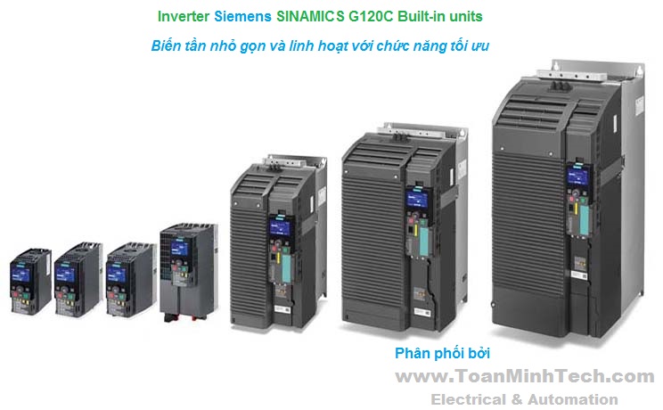
The CU310‑2 Control Unit that is designed for the communication and open-loop/closed-loop control functions of a SINAMICS S120 (AC/AC) is combined with the PM240‑2 Power Module (can be used from firmware V4.8) to create a high-performance single-axis drive. A PROFINET (PN) variant and a PROFIBUS (DP) variant are available for fieldbus communication.

The CompactFlash card contains the firmware and parameter settings. The CompactFlash card is plugged into the appropriate slot on the CU310-2 Control Unit.
A CU310-2 Control Unit can perform the communication, open-loop and closed-loop control functions for one Power Module. The performance expansion is not required in this case.
In addition to the firmware, the CompactFlash Card also contains licensing codes which are required to enable firmware options.
In addition to the Article No., the following firmware options can currently be ordered:
- Safety Integrated Extended Functions, order code F01
After the appropriate license has been purchased via the WEB License Manager available on the Internet, firmware options can also be subsequently enabled.
Further information is available on the Internet at
http://www.siemens.com/automation/license
1) For further information, see https://support.industry.siemens.com/cs/document/104020669
The CU310‑2 Control Unit has the following connections and interfaces as standard:
- Fieldbus interfaceThe status of the CU310-2 Control Unit is indicated using multi-color LEDs.
A BOP20 Basic Operator Panel can also be snapped directly onto the CU310‑2 Control Unit for diagnostics.
As the firmware and parameter settings are stored on a plug-in CompactFlash card, the Control Unit can be changed without the need for software tools.
1) A 24 V supply voltage must be connected to terminal X124 for the digital outputs to be used.
The CU310‑2 Control Unit drives Power Modules in blocksize format via the PM‑IF interface. DRIVE‑CLiQ motors or Sensor Modules (SMC) can also be connected to the integrated DRIVE‑CLiQ socket to permit the operation of motors without a DRIVE‑CLiQ interface.
With the BOP20 Basic Operator Panel, parameters can be changed directly on the device. The BOP20 Basic Operator Panel can also be snapped onto the CU310‑2 Control Unit during operation to perform diagnostics.
The CU310‑2 Control Unit and other connected components are commissioned and diagnosed with the STARTER commissioning tool. The CU310‑2 Control Unit requires a CompactFlash card with firmware V4.4 or higher.
A CU310‑2 PN Control Unit communicates with the higher-level control system using PROFINET IO and the PROFIdrive V4 profile.
The SINAMICS S120 drive system with the CU310‑2 PN Control Unit then assumes the function of a PROFINET IO device and can perform the following functions:
A 24 V supply voltage must be connected to terminal X124 for the digital outputs to be used. A CompactFlash card with firmware version V4.4 or higher is a mandatory requirement for operation of the CU310‑2 Control Unit.

Connection example of CU310‑2 Control Unit
|
|
CU310‑2 Control Unit |
|---|---|
|
PROFINET |
6SL3040-1LA01-0AA0 |
|
Current requirement, max. At 24 V DC, |
0.35 A for CU310‑2 + 0.5 A for PM240‑2 Power Module |
|
Conductor cross-section, max. |
2.5 mm2 |
|
Fuse protection, max. |
20 A |
|
Digital inputs |
In accordance with IEC 61131‑2 Type 1 5 floating digital inputs 8 bidirectional non-floating digital inputs/digital outputs 3 parameterizable, fail-safe digital inputs (floating) or alternatively 6 parameterizable digital inputs (floating) 5 bidirectional floating digital inputs/outputs |
|
-3 ... +30 V |
|
-3 ... +5 V |
|
15 ... 30 V |
|
3.5 mA |
|
|
|
50 μs |
|
100 μs |
|
|
|
5 μs |
|
50 μs |
|
1.5 mm2 |
|
Digital outputs (continuously short-circuit proof) |
8 bidirectional non-floating digital inputs/digital outputs |
|
24 V DC |
|
500 mA |
|
|
|
150 μs/400 μs |
|
75 μs/100 μs |
|
1.5 mm2 |
|
Analog input |
The analog input can be switched between current input and voltage input |
|
-10 ... +10 V; Ri > 100 kΩ Resolution: 12 bits + sign (referred to the maximum range that can be resolved -11 ... +11 V) |
|
-20 ... +20 mA; Ri > 250 Ω Resolution: 11 bits + sign (referred to -22 ... 22 mA) Max. range that can be resolved: -44 ... +44 mA |
|
Encoder evaluation |
|
|
|
|
570 Ω |
|
16 mA |
|
24 V DC/0.35 A or 5 V DC/0.35 A |
|
300 kHz |
|
100 ... 250 kBaud |
|
30 bits |
|
|
|
100 m (328 ft) (only bipolar signals permitted) 3) |
|
100 m (328 ft) for unipolar signals 300 m (984 ft) for bipolar signals 3) |
|
100 m (328 ft) |
|
Power loss |
<20 W |
|
PE connection |
M4 screw |
|
Dimensions |
|
|
73 mm (2.87 in) |
|
|
|
191 mm (7.52 in) |
|
187 mm (7.36 in) |
|
75 mm (2.95 in) |
|
Weight, approx. |
0.95 kg (2.09 lb) |
|
Certificate of suitability |
cULus |
1) The specified delay times refer to the hardware. The actual reaction time depends on the time slot in which the digital input or output is processed.
2) In order to use the digital outputs, an external 24 V power supply must be connected to terminal X124.
3) Signal cables twisted in pairs and shielded.
(Nguyễn Thảo Trường - http://DienElectric.com theoSiemens)